


In the infrastructure of RF Overlay on PON, the choice between EDFA vs EYDFA (Erbium-Doped Fiber Amplifier vs. Erbium-Ytterbium Co-doped Fiber Amplifier) is a critical engineering decision. For network planners, these devices represent two distinct physical toolsets with vastly different noise characteristics and power scaling limits. Understanding the “First Principles” of EDFA vs EYDFA is essential to delivering stable 4K/8K video across complex fiber networks.
Based on our field observations across global ISP networks, this article explores the logic of optical cascade architecture and identifies the systemic bottlenecks that lead to MER (Modulation Error Ratio) and CNR degradation. We will move beyond marketing specs to address the real-world engineering challenges that often cause high-end hardware to be blamed for site-specific failures.
1. Technological Fundamentals: EDFA vs EYDFA Purity
The success of an optical link is governed by the Noise Figure (NF). To build a robust network, you must first understand the fundamental “personality” of each amplifier type and where they fit in the signal chain.
1.1 Standard EDFA: The Precision Gatekeeper
A standard EDFA utilizes single-mode 980nm pump lasers to excite Erbium ions within a single-clad fiber. Because the pump and signal are both confined to a narrow core, the energy transfer is highly efficient and predictable.
- Ultra-Low Noise: It maintains a Noise Figure (NF) typically below 4.5dB.
- The Role: It is designed for signal “grooming.” Because it introduces minimal ASE (Amplified Spontaneous Emission) noise, it is the ideal first stage for any cascade to ensure the highest possible signal niose ratio (SNR) before the signal reaches high-split distribution.
1.2 EYDFA: The High-Power Engine
The EYDFA is the workhorse of the “last mile.” It utilizes Erbium-Ytterbium co-doped fiber and Double-Clad Fiber (DCF) technology. Ytterbium ions act as a sensitizer, absorbing massive amounts of multi-mode pump energy and transferring it to the Erbium ions.
- Extreme Power: It can achieve total outputs exceeding 40dBm, supporting massive splitting ratios like 1×128 or 1×256.
- The Trade-off: The complex energy transfer and multi-mode pumping inherently raise the Noise Figure (typically 5.5dB – 6.5dB). It is a “Booster,” designed for mass coverage rather than extreme spectral purity.
2. The Art of Cascade: Engineering the EDFA vs EYDFA Link
A frequent engineering question is: “In what order should I connect my amplifiers to maximize the link budget?” While every network is unique, the laws of noise accumulation suggest a clear hierarchy of cascade architectures.
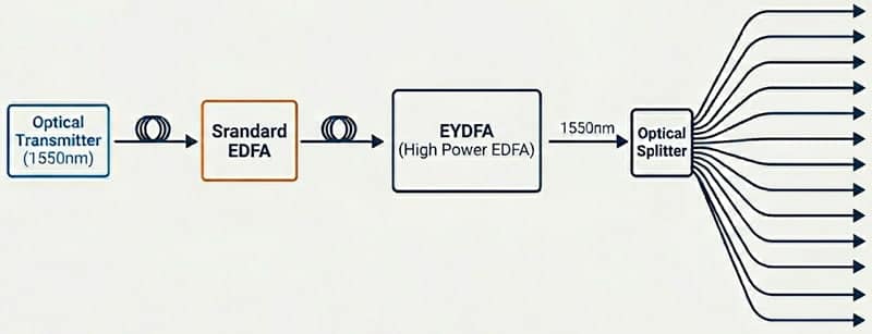
2.1 The “Gold Standard” (2-Stage): Standard EDFA → EYDFA
This is the primary recommendation for high-performance networks. In this setup, the Standard EDFA acts as a high-sensitivity pre-amplifier. It takes the relatively weak signal from the optical transmitter and boosts it while the signal is still “clean.” The EYDFA then takes this healthy, high-MER signal and provides the brute force needed for the final distribution. This setup consistently yields the highest MER at the subscriber’s ONU.
2.2 The “Reliable Long-Haul” (3-Stage): Standard EDFA → Standard EDFA → EYDFA
This is often used when the headend is located far from the distribution hub. Using two stages of low-noise pre-amplification preserves the signal’s integrity over long fiber spans before the final booster stage. As long as the input to each stage is carefully managed (typically within the -3dBm to +2dBm range), the cumulative MER remains stable.
2.3 The “High-Risk Path”: Standard EDFA → EYDFA → EYDFA
This is the least recommended setup, yet it is frequently found in regions where engineers rely on “power” over “purity.” Cascading two EYDFAs back-to-back creates a cumulative noise “snowball.” The second booster stage amplifies the already high ASE noise floor of the first booster. Even if the optical power meter shows a strong reading, the Modulation Error Ratio (MER) may have already crashed below the failure threshold.
3. The “There Silent Killers”: Why EDFA vs EYDFA Logic Fails in the Field
In many regions, we observe a recurring pattern: high-end hardware is installed, but performance targets are missed. Often, this is not a equipment defect, but a result of entrenched bad habits and a lack of standardized operational training. Even in European and North American markets where installation environments are superior, these “silent killers” can still compromise a network.When troubleshooting EDFA vs EYDFA performance issues, these external factors are often the root cause.
A. Source Pollution: “Garbage In, Garbage Out”

An optical amplifier is a transparent medium; it cannot “repair” a broken or noisy signal. A common mistake is using a Directly Modulated Transmitter for high-channel loads or long distances. DML units suffer from inherent “chirp” and dispersion. If the transmitter’s output MER is already low (e.g., 32dB), the EYDFA will amplify that noise with perfect fidelity. Expecting an amplifier to “clean up” the signal is unscientific. For high-density subscriber pools, an Externally Modulated Transmitter is the only professional choice.
B. The Cleanliness Crisis & Phase Noise
Optical cleanliness is a physical requirement, not a suggestion. A single fingerprint or speck of dust on an APC connector creates a micro-reflection. In high-power environments (>18dBm), these reflections generate Phase Noise. While a power meter might still show a “good” reading, the digital MER will plummet because the signal’s phase is being jittered. Many field engineers skip the cleaning protocol, leading to “unexplained” BER spikes that are entirely preventable with absolute alcohol and proper wipes.
C. Environmental Abuse: The Cabinet Trap
Precision optics require a stable environment (~25°C). We frequently see EYDFAs installed in unventilated outdoor cabinets subjected to extreme tropical heat. High heat accelerates Arrhenius Aging of the laser diodes. This doesn’t just shorten the equipment’s lifespan; it actively worsens the noise figure and gain stability during the hottest hours of the day. A “stressed” machine is an unreliable machine.
P.S.: In some developing regions, the electrical grid is a chaotic environment characterized by high-frequency noise and voltage ripples. While professional amplifiers feature internal filtering, excessive power ripples can creep into the laser driving circuitry in extreme cases. This interference manifests as subtle jitter in the optical output, degrading the CNR. A stable, regulated, and properly grounded power supply is vital—hardware can only filter so much before the environment takes its toll.
4. Technical Summary: EDFA vs EYDFA Engineering Standards
| Network Condition | Recommended Engineering Practice |
|---|---|
| Cascade Priority | Standard → EYDFA (The balance of Purity and Power) |
| Input Signal Quality | Must be verified at the headend; Use External Modulation for >10km |
| Port Maintenance | Mandatory cleaning before EVERY insertion; No exceptions |
| Power Management | Regulated AC/DC; High-frequency ripple suppression required |
Frequently Asked Questions: EDFA vs EYDFA Optimization
Q: What is the optimal cascade architecture for EDFA vs EYDFA?
A: The “Gold Standard” is a two-stage cascade: a Standard EDFA (Pre-amp) followed by an EYDFA . This ensures the signal is amplified with the lowest possible noise figure before being distributed at high power.
Q: Why is my MER dropping significantly after the EYDFA stage?
A: MER degradation is rarely a hardware defect. Common causes include “Source Pollution” from DML transmitters, ASE noise accumulation from cascading EYDFAs improperly, or contaminated connectors causing phase noise.
Q: How does power grid quality impact EDFA vs EYDFA performance?
A: High-frequency ripples and surges in unstable grids can introduce jitter into the laser driving circuitry, resulting in unstable CNR and long-term laser degradation.
Conclusion: Science Over Shortcuts

The distinction between EDFA vs EYDFA is a matter of architectural strategy, not just “buying more power.” While modern hardware provides incredible redundancy, it cannot override the laws of physics. If the signal source is noisy, the connectors are dirty, the grid is unstable, or the machine is overheated, the performance will suffer.
To deliver a flawless 4K/8K experience, engineers must move away from “bad habits” and start investing in standardized system integration. Respect the cascade order, maintain your fiber ports, and ensure your transmitter is up to the task. Build your network on science, not shortcuts.