


In high-density Hybrid Fiber-Coaxial (HFC) networks, maintaining crystal-clear RF video delivery requires rigorous control over non-linear intermodulation products. For network engineers and RF hardware exporters, managing CTB and CSO Distortion is the ultimate benchmark of link quality. When deploying multi-channel analog or high-order digital QAM signals over long distances, these distortions directly dictate the Carrier-to-Noise Ratio (CNR) at the subscriber’s terminal node.
The Physics of Non-Linearity: What Drives CTB, XM, and CSO?
When multiple RF carriers pass through non-linear active components—such as the laser diodes in a CATV transmitter, the erbium-doped fiber inside an EDFA, or the photodiode within an optical receiver—they corporate to generate unwanted harmonic frequencies at specified intervals. These intermodulations degrade the clear spectral threshold of the transmission plant.
1. Composite Second Order (CSO) Distortion
CSO distortion is caused by the combination of two frequencies, resulting in sum and difference beats clustering around the visual carrier. This behavior shifts linearly on a power basis. In a typical channel allocation plan, these secondary harmonic allocations scale systematically across cascading active networks. Consequently, tracking these secondary tracking profiles is an essential step when assessing cumulative CTB and CSO Distortion behavior across a multi-stage active network.
2. Composite Triple Beat (CTB) Distortion
CTB is defined as the sum of the resultant third-order beats produced by all combinations of three frequencies that occur exactly within a specified channel frequency band. In multi-channel systems utilizing push-pull configuration architectures, CTB acts as the primary limiting performance factor.
3. Cross Modulation (XM) Distortion
XM distortion manifests when the modulation from one independent RF carrier is imposed onto another adjacent carrier within the plant. The mathematical addition properties of XM match those of CTB, as both scale exponentially on a voltage basis across active transmission systems. Because XM scales alongside third-order products, minimizing it goes hand-in-hand with deploying hardware optimized to compress global CTB and CSO Distortion margins.
Mathematical Calculations for Active Cascades
To evaluate how these non-linearities accumulate as signals pass through multiple RF amplifier stations or cascading active hardware nodes, network designers must utilize strict logarithmic summation formulas. Accurate link modeling prevents unpredictable compounding of CTB and CSO Distortion metrics at the end of a long-haul coaxial run.
1. Composite Triple Beat (CTB) Cascading Ratios
Because CTB builds up on a voltage basis, cascading identical or dissimilar nodes expands the overall distortion layout exponentially.
To add similar CTB ratios:
To add dissimilar CTB ratios:
Where:
• CTB0, CTBn = CTB (dB) of a Single Amplifier (n = 1, 2, 3, …N)
• CTBS = System CTB (dB)
• N = Number of amplifiers in cascade
Important Rules of Thumb:
• Doubling the number of amplifiers with identical CTB ratios degrades the total system CTB by exactly 6dB.
• Reducing the amplifier output level by just 1dB improves the system CTB by approximately 2dB.
2. Cross Modulation (XM) Cascading Ratios
Since XM also adds on a strict voltage basis across multi-stage active networks, its calculations mirror those of third-order triple beat distortions.
To add similar XM ratios:
To add dissimilar XM ratios:
Where:
• XM0, XMn = XM (dB) of a Single Amplifier (n = 1, 2, 3, …N)
• XMS = System XM (dB)
• N = Number of amplifiers in cascade
• Doubling the cascade count with identical XM metrics drops performance by 6dB. Reducing system output by 1dB yields a 2dB optimization margin.
3. Composite Second Order (CSO) Cascading Ratios
Unlike third-order anomalies, secondary intermodulation distortions add strictly on a power basis rather than a voltage basis, scaling down the accumulation profile curve.
To add similar CSO ratios:
To add dissimilar CSO figures:
Where:
• CSO0, CSOn = CSO (dB) of a Single Amplifier (n = 1, 2, 3, …N)
• CSOS = System CSO (dB)
• N = Number of amplifiers in cascade
Important Power-Basis Rules:
• Every time you double a cascade of similar amplifiers, system CSO degrades by 3dB.
• Reducing amplifier output specifications by 1dB improves system CSO performance margins by exactly 1dB.
Graphical Estimation of Combined Distortion Values
When engineering mixed active networks with differing noise profiles, technicians can calculate spatial adjustments manually or leverage specialized subtraction factoring charts. To graphically isolate combined performance margins between two active segments:
- Calculate the exact operational level or CNR difference between the two target active units.
- Locate the corresponding differential point horizontally along the baseline axis of the combination curve graph.
- Identify the intersecting vertical vertical subtraction factor intersection metric.
- Subtract that derived subtraction value from the lowest individual hardware baseline score to yield your clean, aggregate system value.
Critical Link Parameters for Multi-Channel CATV Systems
To design an HFC infrastructure that suppresses CTB and CSO Distortion below acceptable thresholds (typically ≥ 65dBc for analog or ≥ 50dBc for digital networks), engineers must evaluate the hardware metrics across the entire lightpath.
| Network Parameter | Typical Target Level | Primary Hardware Constraint | Impact on Picture Quality |
|---|---|---|---|
| CNR (Carrier-to-Noise) | ≥ 51 dB (Analog) / ≥ 38 dB (Digital) | Optical Input Power & Noise Figure | Snowy background, pixelation, or screen freeze |
| CSO Margin | ≥ 65 dBc (Full Channel Load) | Laser Chirp & Photodiode Symmetry | Diagonal herringbone lines and color shifting |
| CTB Margin | ≥ 65 dBc (Full Channel Load) | RF Drive Levels & Amplifier Linearity | Severe ghosting, loss of contrast, fuzzy edges |
Mitigating Intermodulation: The Premlink Hardware Solution
At Premlink, our entire engineering philosophy revolves around suppressing CTB and CSO Distortion while optimizing high-power distribution over deep fiber architectures.
1. Headend Precision with Low-Chirp EDFA Architecture
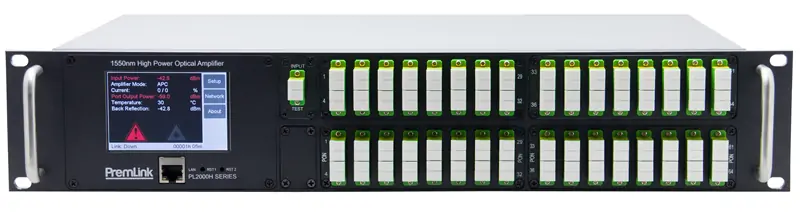
Every amplification stage introduces optical non-linearities through Self-Phase Modulation (SPM). Premlink’s high-power 1550nm PON EDFA series utilizes premium Er-Yb co-doped fibers and advanced internal microprocessors to maintain a strictly flat gain profile. By capping the optical noise figure at an ultra-low ≤ 4.5dB or 5.0dB, our EDFAs deliver massive optical budgets without pushing the fiber core into thresholds that cause severe CTB and CSO Distortion expansion.
2. High-Linearity down to the Subscriber Optical Receiver
The conversion of light back into RF energy at the home is a notorious bottleneck for harmonic generation. Premlink’s FTTH Optical Receivers utilize highly symmetrical PIN photodiodes paired with specialized GaAs push-pull amplifier modules. This integration ensures that even at fluctuating optical input powers (from −10dBm up to +2dBm), the internal circuitry automatically compensates for slope and tilt, keeping CTB and CSO Distortion firmly within carrier-grade tolerances.
By treating the HFC network as a cohesive, closed-loop transmission link, Premlink enables ISPs to scale their multi-play services without sacrificing analog tier premium quality or digital channel data throughput.
Expert FAQ: Solving CTB and CSO Distortion Technical Bottlenecks
Q: Why does increasing the channel count make CTB and CSO Distortion significantly worse?
A: CSO increases linearly with the number of channels, but CTB grows exponentially on a voltage basis. As you add more carriers, the total composite RF voltage driving the internal laser or amplifier components pushes the linear threshold curves to saturation bounds, multiplying third-order harmonic development.
Q: How do Premlink’s hot-swappable dual power supplies protect signal distortion metrics?
A: Inconsistent voltage input creates sub-frequency ripples that directly alter amplifier bias profiles. Premlink’s carrier-grade dual power components provide flat, ripple-free current, entirely eliminating auxiliary voltage fluctuation anomalies from shifting your composite beat margins.
Q: Can adjusting the optical input power at the node improve my CSO scores?
A: Absolutely. If input margins push higher than +2dBm, physical photodiode saturation introduces immediate second-order harmonic drops. Utilizing internal attenuation fields ensures active chips remain inside their designated sweet spot, maximizing simultaneous CNR and intermodulation protection.